AUTOCORD : the Minolta's TLR
by Fred
The focus lever : maintenance - repair
(part 2)
Manufacturing
6) Production of the new lever : first step.
a) with copper wire :
Cut two 150 mm long pieces of copper wire.
Turn them around the ring aluminum to give them shape.
Shorten one end of each wire so that the ends do not touch, it must remain a space of a half mm.
On the wooden board, solder the ends of each wire, they must touch together.
On the lump hammer, flatten the copper rings with the engineers hammer to create a light flat.
Place four welding points on each thread.
Place your copper rings one on the other, keep apart from one another the weld points already welded.
Solder the rings by welding points one after the other, making sure to keep the rings well centered between them.
Allow to cool after each weld.
Solder intermediate areas one after another by cooling each time.
b) with a piece of 42 mm diameter copper pipe :
Saw a straight slice of 4 mm thick.
Practice a rectangular notch 7 x 1 mm centered on the wafer.
File the burrs with a round file.
7) New lever : second step.
Cut a piece of copper pipe 7 mm long
Under the blowing flame open the pipe and make it flat.
20 mm from an end fold at 90 ° .
At 3 mm of this fold , fold again to 90 ° in the other direction like a stair step .
Cool the piece.
At 4 mm of the second fold , cut off the excess .
Check if the piece enters the available space of the camera ( replace the printed focus scale plate if necessary).
Adjust if necessary.
At the small end , make a hole of 2 mm at the center. Remove burrs .
File the corners to round .
Solder the longest part on the edge of the rings, between the rings .
Check the flatness of the assembly.
If you have a piece of pipe , solder in the notch.
Solder the button in the hole.
Placing
8) Placing the new lever .
Replace the bronze tray in place, tighten the three screws.
Check the alignment of aluminum ring vs bronze helicoïd marks (= position ' to infinity ').
The helicoïd screws holes must coincide with the mounting holes of the black block :
one above, the two other oriented at 120 ° ( as an inverted Y - see the green arrows) .
Put the copper ring on the aluminum ring.
If you have worked well , it is slightly smaller so as to tighten the aluminum ring.
Before you crimp the copper ring ,
orient it to position ' to infinity ' ( against the stop limit switch) .
Check all alignments.


Reassambly
9) Reassembly of the camera.
If you have not already done so, turn the printed focusing plate in place : two screws.
Put the aluminum framework in place : four screws.
Put the black block in place : three screws.
Test the operating focus lever : the block rises and falls.
The lowest position corresponds to the 'to infinity' position.
In the up position, check the tightening of screws.
Place the spacers, the plates and ring in the correct order.
The plates must have their slot engaged on levers
in the right side of the unit (crank side, see photo opposite).
The slot of the lower plate is lodged on the lower tenon,
the one that moves amply with the crank (red arrow).
The slot of the upper plate is lodged on the upper tenon,
the low displacement one (green arrow).
Place the shutter. Check its correct positioning : wedging pin,
cocking lever (variable depending on the shutter model).
Photo : Michael
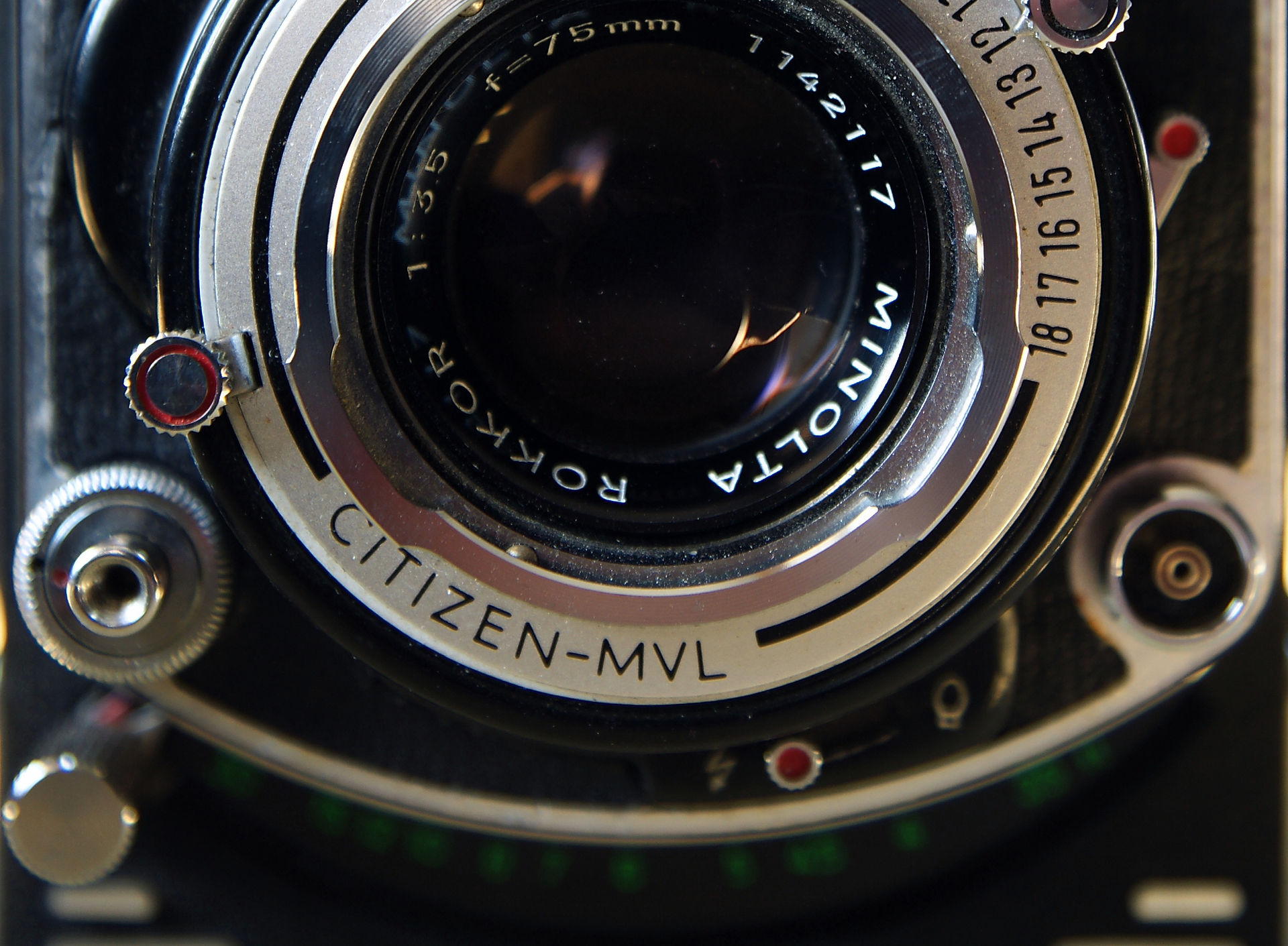
Warning : for the CITIZEN MVL shutter, make sure that the cocking lever of the shutter is positioned correctly before continuing, at the risk of bending it in the next step.
Photos : Michael
Bad Good
Place the lenses shell (don't need to screw it), check if the shutter speed and diaphragm levers are engaged correctly in their dial nicks (diaphragm and speed must vary when moving levers), keep everything together and turn the camera upside down.
By the opened dark room, screw the fixing ring using the snap ring pliers. Be careful not to scratch the lens.
Check installation : test the crank, arm the shutter, actuate the trigger, operate the diaphragm, trigger a flash
(connected to the block outlet).
If something is not working properly, remove, check, fix and repeat.
Checking
10) Check of focus point.
You should check that the focus point is well on the film plane.
Open the back cover, place a frosted glass on the frame where the film passes (= film plan).
Stand in front of a scenery composed of near and far objects, to infinity.
Adjust the focus lever to infinity and see the image on the frosted.
If the objects at infinity are net and clear, it's all good. Go 5 lines down : checking the viewing lens.
If the objects at infinity are blurred and near objects are clear, the point of sharpness is behind the film plan.
If all objects are blurred, the point of sharpness is in front of the film plan.
In either case, you must correct the positioning of the focus lever and/or helicoid bronze (see point 8).
Repeat point 10 until it's right.
Also check the setting of the viewing lens.
Adjust the focus lever to infinity, observe a distant object in the viewfinder. Help yourself with the magnifying glass.
If it appears very clear, it's good.
If it is not clear, unscrew the screw on the side of the lens sighting with a small and thin screwdriver.
Turn the lens in one direction or the other to get the focus of your object.
Tighten the screw.
Finalizing
11) Finish up with your camera.
Place the black cone inside the dark room.
Put the lenses shelf in place : five screws (the lower one has a different head) or four screws on late models.
If you had to take it off, place the synchro flash selector button.
Paste the leatherette with some photo double-sided sticky labels or some kind of school stick glue.
Now your camera focus lever is repaired.
dubble copper wire lever
Crimp your brass ring on the aluminum ring ,
well hold it in place while you strike small blows around with the hammer.
If your ring goes too easily and does not squeeze, it is too large;
It is necessary to reduce its diameter :
-) adding solder to the inside of the ring
-) or desolder everything and slightly reduce the length of the wires, resouder the whole.
If your ring does not pass at all, it is too small; check the inside of the ring, reduce excess welds if there is any.
Make sure that your lever moves from one side to the other
without embarrassment ; also with the printed focus sclae plate replaced.
Adjust if necessary.


